


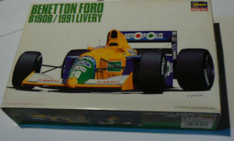
Benetton-Ford B190B
Benetton Ford B190B, F1 season 1991
Go to latest entry (december 5, 2010)The Story:
After two unsuccessful years at Lotus, Piquet had signed a contract with Benetton at the end of 1989. After a (according to some people surprisingly) successful 1990, with 2 wins in the last 2 races of the season, Piquet was offered a contract for 1991 by Benetton.The car I'm going to build, the B190B, ran for the first 2 GP's of 1991 while waiting for the John Barnard drawn B191.
The B190B was in fact the same car as Benetton had used the previous year. Only the livery was changed.
Although the car wasn't new, it still was relatively successfull during those first GP's of 1991. Nelson Piquet scored a nice third and fifth place during those 2 GP's.
The Project:
This kit is the fifth project I'm taking on since restarting this hobby.It will be the first Hasegawa kit I'll be building. And on top of that, it will also be the first F1 kit I'm building in the "unholy" 1/24 scale.
This build will be the second build for my Nelson Piquet collection.
The Kit:
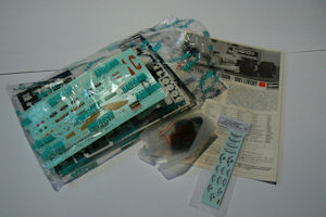
About The Kit:
All the previous F1 kits that I've build have been from Tamiya. So I was a bit curious about the quality of the parts and the fitment of the parts compared to Tamiya.And I must admit, I am evenly disappointed and surprised by the quality.
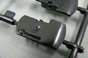
Surprised, pleased may be a better word, I was concerning the quality of the monocoque and engine cover. Looks very nice. Good quality. A nice touch is the fact that the borders for the different colours are marked with a slightly raised rib on the body, making masking for the paintjob very easy. Well thought out.
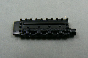
Pleased also with the quality of the valve covers for example (left picture, below). Lots of detail. In my opinion one of the best parts of this kit.
As I already mentioned, other parts of this kit where quite a let down, considering the quality of some of the other parts in this kit.
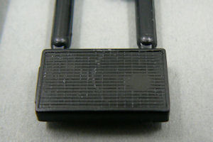
Especially the several radiators in this kit are not that good. The pattern on the radiators is very faint, and on almost all of them a very prominent ejectorpin mark is present on the part.
Ejectorpin marks are also very visible on the parts for the front and rear wings. And the crap-de-la-crap of this kit must be the front brake cooling ducts. A giant sink mark present on a very visible location.
Almost unbelievable that Hasegawa managed to combine such well thought out and very detailed parts with some very crap ones...
But hey, that's the challenge for the model builder, right ? And anyway, not that big a drama. All those parts I mentioned can be repaired quite easily. It's only a shame that this extra work should be necessary in the first place, because in my opinion this could have been avoided by Hasegawa.
Anyway, enough complaining, on to the actual build report !
May 1, 2008 - Start of the build
The start of the project isn't very spectacular.After studying the manual I decided to glue together several parts that will be the same colour.
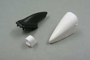
Hasegawa has decided to split the nosecone, airbox and rollbar lengthwise. Looking at Tamiya kits from the same era, I think that this could have been done differently. I do know that for injection molding the solution from Hasegawa is the easiest one. Only setback is that is means more work for me to get rid of the joint lines. But it's not something that can't be done, so it's not such a big deal. Just one of those small things that make you realise what makes Tamiya so good...
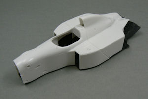
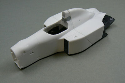
I also did a bit of testfitting how the monocoque and engine cover would fit to the bottom of the car. Looks promising, although you might think otherwise, when looking at the picture to the right (below). I think it looks promising.
Apart from the above there is not much to be shown yet.
The build report for this project can also be followed on f1m.com as this project is an entrant for the Group Build on that site.
August 1, 2008 - Preparations
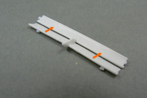
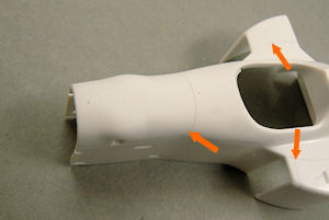
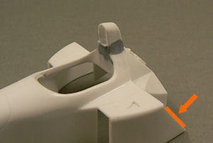
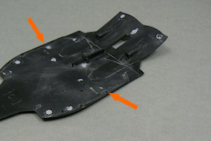
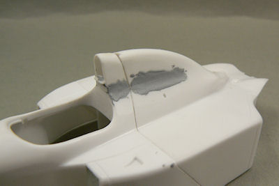
After so much time, there is still not a single part of this kit that has been painted.First job has been to eliminate the hardly visible mould lines and deepen the panel lines (orange arrows in images below).
Apart from that, I also had to remove the incredible convenient borders that were on the monocoque to mark the borders of the different colors. Sadly those borders only apply for the 1990 livery of the car, so could not be used for this version.
Removing those lines wasn't much work, but it had to been done nonetheless.
However most of the work has gone into filling all the sink marks on the various parts. The parts shown below are only a selection...
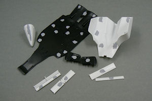
As you can see in the images above, I only bothered to fill the sink marks that are visible once the model is fully assembled. Lazy me, huh...
Apart from all the filling and sanding I also managed to do some fun work (well, at least that's how I see it).
As this kit is from Hasegawa, the colours indicated in the instructions are from Hasegawa too. But as they're not very easy to come by in the Netherlands, I decided to use colours that are freely available to me.
The green colour used was relatively simple, as it is the same colour that Tamiya has indicated in their instructions for the Benetton B188 car.
The yellow was also simple. I'll be using Camel Yellow from Tamiya (spraycan), as this car was Camel sponsored and therefore it is logical to assume that the yellow colour should be Camel Yellow.
The blue was a bit more difficult. In the various colour charts I've found on the internet, I couldn't find an alternative for the Hasegawa colour indicated. So I started mixing some colours myself.
With the help of some reference pictures I've decided that the blue should be ultramarine blue (36151) from the Revell Aqua Color series.
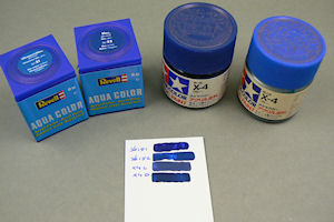
Funny by the way: I have two jars of X4 blue from Tamiya. Both gloss paints, but as can be seen from the samples above, quite different from each other (and yes I did stir the paint thoroughly before painting).
A potential problem
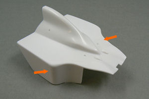
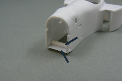
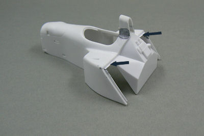
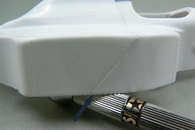
While testfitting the various parts I encountered a potential problem.The fitment of the rear bodywork is not perfect as can be seen in the pictures below. The walls of the rear bodywork face slightly inward so there is a small gap between the front and rear part of the bodywork (see arrows).
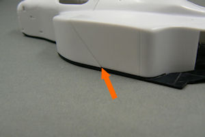
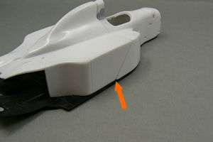
While the fitment on the left picture might seem not so bad, on the right picture it is quite a gap.
There are several solutions to the problem. I can glue the rear bodywork to the undertray. This would probably give the best fitment, but than the engine can not be seen anymore, which would be a bit of a shame as it will be quite nice looking (I suspect).
On the other hand, once the pictures are taken, the rear bodywork will probably never been taken off anymore, so why bother ?
Another solution is bending the vertical walls a bit to the outside while applying heat (like from a hairdryer). I have used this technique a few times with success. But not on a symmetrical object, so getting everything looking right might be a bit of a challenge.
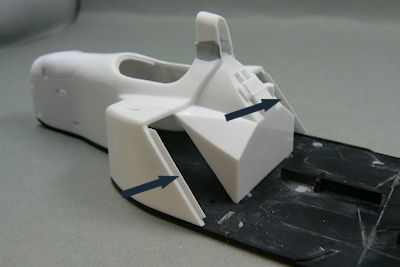
The most likely solution I will try (first) is glueing small strips of sheet styrene to the front bodywork (the inside of the sidepods, indicated in the left picture below) which will function as a sort of guide for the rear bodywork. Because I do like the idea of being able to remove the bodywork to show the engine.
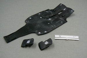
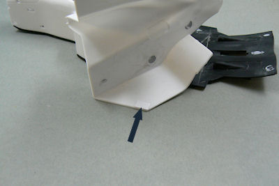
For some reason Hasegawa has provided some holes in the undertray where nothing is mounted (right picture below). Which is rather odd. I first thought that mounting pins from the rear bodywork should fit in those holes, but the rear bodywork doesn't have any mounting pins... It might be an option to make some pins of my own, to get the rear bodywork to fit to the undertray.
If this first idea doesn't work, I will try adding mounting pins instead.
More to follow in the next update.
2010, December 5 - Primer approach
As can be seen in the previous update, the fitment of (especially) the rear bodywork left something to be desired. Below are several pictures displaying how I have tackled that problem.First picture shows a spacing bar in the front of the body. This was necessary because I'd removed the mounting pins from the nosecone. And to get the sidewalls of the nosecone and the bodywork properly aligned I chose this solution.
On top of that I glued in a small piece of styrene to the bottom of the body to prevent the possibility of looking through the car as the bottom didn't close up this area enough in my opinion.
The second picture shows the styrene strips I glued to the front part of the sidepods.
The third picture shows the rear bodywork and a few styrene strips I glued onto the bodywork, to push the bottom parts to the outside, when fitted over the front bodywork.
In the fourth picture the result of the modifications can be seen.
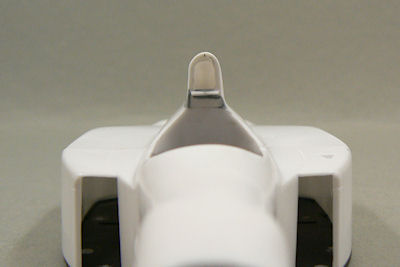
As can be seen from the last picture above, the alignment between the rollover bar and the rear bodywork isn't good.
I tried to solve it by removing and re-attaching the rollover bar. But if I'd moved it any further than I did it could be seen too easily (that the car wasn't symmetric anymore).
But moving the rollover bar wasn't enough however. The problem lies with the rear bodywork which seems to be deformed. I wasn't convinced that I could bend it to shape, so I decided to glue the rear bodywork to the car.
This means that the engine and radiators won't be visible after building. So I won't be detailing them as a result.
Below are several pictures of the car with the rear bodywork glued on.
It wasn't as simpel as glueing it on however. I did have quite some sanding to do, to get the alignment correct.
I must admit that it isn't perfect by a long shot, but I think it is satisfactory.
The following pictures show the progress so far.
The first picture shows the front bodywork with some additional styrene so the rear bodywork can be glued to the front bodywork easily.
The second picture is a picture from the front of the car showing the rollover bar (and the fact that is sits slightly to one side).
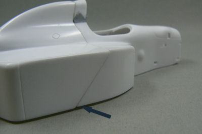
The third picture shows the rear bodywork glued to the front. Front and rear bodywork are dryfitted onto the undertray. A slight opening is visible here (also on the opposite side) and will have to be closed. For the I glued a piece of styrene to the bodywork and sanded it flush with the undertray.
The fourth picture shows the result of this.
The fifth picture shows the left side of the airbox which had to be smoothed out after the airbox had been sanded flush with rollover bar.
There are only some slight repairs left to be done and than the primer can be sprayed onto the car.
Find out more about this in the next update.